Corrugator machine alignment using ParAlign and a Faro laser tracker
Fluke Reliability’s alignment team traveled to a client’s corrugated board production plant to perform an alignment service on a corrugator machine. Implementing a new methodology that required using the Pruftechnik ParAlign Roll Alignment system in combination with a Faro Laser Tracker, the team measured the entire wet-end, encompassing 126 rolls, and all 15 hot plates in a single weekend. Adding the Faro Tracker applications to the ParAlign procedure gave the Fluke Reliability Service team the resources to provide a comprehensive alignment, as opposed to more limited conventional alignment methods.

Figure 1. Corrugated board production. Illustration by Fefco.org
About the ParAlign technique
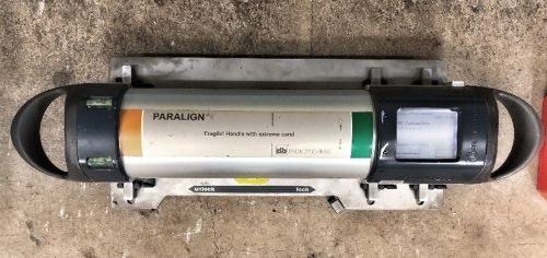
The ParAlign device encompasses three ring-laser gyroscopes positioned in the x, y, and z directions, respectively. The gyroscopes, a product of Honeywell, are often used in military aerospace/aircraft applications. The gyroscopes measure the roll, pitch, and yaw of the ParAlign device as it is swept across the circumference of the roll. A minimum of 20 degrees of sweep is needed to measure the center axis of the roll.
As points are collected along the arc, the corresponding software will equate an angle through geometrical equations and utilize the length from bearing to bearing of each roll to determine the horizontal and vertical offsets. The graphical, easy-to-interpret reporting format allows mechanics to easily understand what adjustments need to be made and to then properly make the corrections with precision shims and dial indicators. Each roll measurement takes roughly 30 seconds, which allows entire machines to be measured in less than six hours.

Figure 2. The Pruftechnik ParAlign Roll Alignment system
The reporting is a two-dimensional representation of the parallelism of rolls relative to the reference rolls. For the corrugator industry, the reference is typically referred to as the bottom preheat of the triple stack. As an example, Figure 3 displays three measured rolls with their respective vertical and horizontal offsets. The blue roll indicates the reference roll. The green circle represents the operator side of the machine and the red circle represents the drive side. Interpreting the results, the roll on the right is positioned 0.069″ high and 0.001″ left of the reference roll on the operator side. To adjust this roll, one would adjust the operator side of the roll down 0.069″. Additionally, if an adjustment is only available on the drive side, a 0.069″ shim can be placed under the drive side bearing of the roll to correct the misalignment.
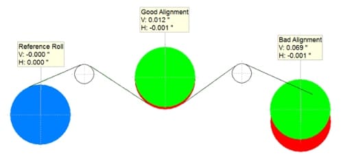
Figure 3. ParAlign reporting example of three rolls with vertical and horizontal offsets.
The software can change the reference roll at any time to show all relative offsets to the newly selected roll. In particular, this comes in handy when observing the misalignment in certain sections, such as modul facers with corresponding splicing units.
If you'd like more information on Pruftechnik, click here to go to the Contact Page.
In-depth description of the corrugator alignment serviceThe wet-end of the corrugator housed a total of 126 rolls, all of which were measured within the first five hours of Day 1. The crew spent the rest of the first day making adjustments to 37 of the rolls found to be initially misaligned.
- The rolls were adjusted by the in-house maintenance staff to the tolerance of +/- 0.030″ in the vertical and horizontal directions.
- The ParAlign segment of the service involved measuring all rolls located within components from the double backer to the first splicing unit.
- Of the 89 rolls measured, 45 were adjusted and re-measured to determine final position.
- The rolls were adjusted to achieve a tolerance of +/- 0.030″.
- The rolls that were not able to meet the tolerance were either constricted due to a pre-existing framework layout or bolt-bound conditions.
Major adjustments included lifting the operator side of the tail pulley framework roughly 0.150″ to align the beginning of the double backer to the bottom preheater of the triple stack. Once this adjustment was completed, the team used the Faro Laser Tracker to measure the leading edge of the first hot plate and the trailing edge of the last hot plate to cultivate an ideal plane to use as a reference for the hot plate alignment.
![]()
Figure 4. The Faro Laser Tracker.
The objective was to align the leading edge of each hot plate so that it lay no more than 0.010″ below the previous plate. Initial measurements of the plates indicated that the plates did not gradually incline as they should, but rather, they drooped in the middle to form an arc. This data was collected by measuring each corner of each hot plate and relating its position to the generated ideal plane. Correcting the misalignment required some plate corners to be adjusted over 0.100″. The alignment of the plates can be viewed in the corresponding images below.
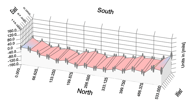
Figure 5. Initial hot plate measurements taken with the Faro Laser Tracker
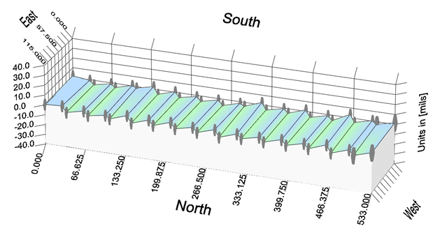
Figure 6. Final hot plate measurements (after adjustments)
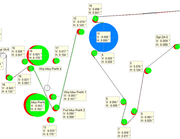 Figure 7: Screen capture of initial ParAlign results. The green circle represents the operator side of the machine and red represents the drive. All offsets are relative to the reference roll (labeled blue). In such an image, one can easily understand the amount of misalignment present as the more red that is seen, the more misalignment there is.
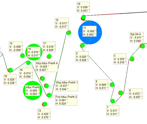
Figure 8. Screen shot of final ParAlign results (after adjustments).
After adjustments were made, each ‘moved’ roll was re-measured to show new positioning. Observing the amount of red that has been removed from the image makes it possible to determine how much misalignment was corrected.
Conclusion
Performing this alignment across the corrugator yielded improvements, including eliminating wrinkle problems, twist warp, and delamination or bonding issues. The client saw a noticeable difference in machine performance and product quality. In addition, the board now lay flat across the machine, using less starch with minimal adjustments needed.
)
)
)